Overview
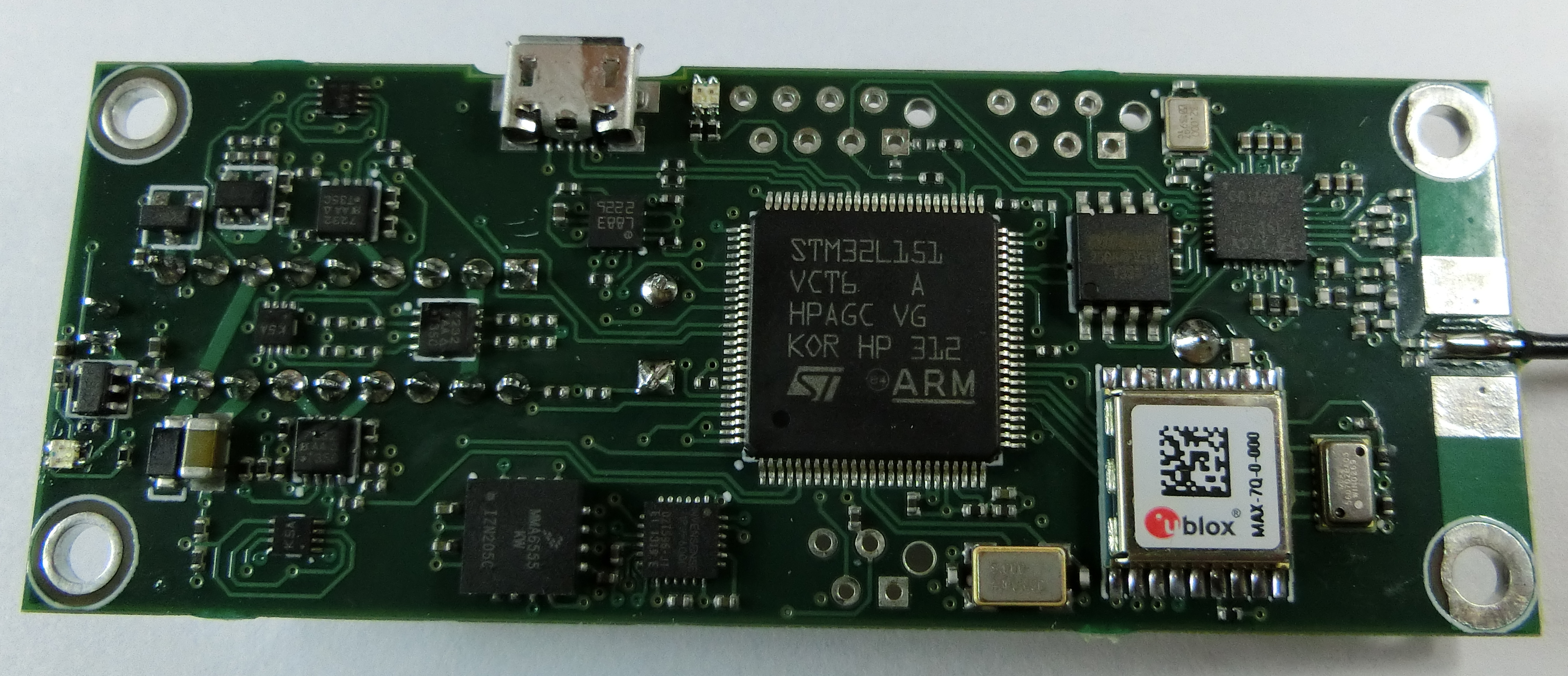
Designed for high performance flights of technically advanced rockets, the TeleMega supports 6 pyro channels, dedicated power busses for the energetic systems, servo outputs, GPS, telemetry, and companion boards.
CAD
Wiring
The TeleMega can be configured for launch in armed mode by starting it with the antenna pointed upwards, or it can be put in idle mode by starting it in any other orientation. TeleMega has two rows of nine screw terminals.
The top terminals 2 and 3 (labeled switch) allow for the connection to an external flight computer, but the two terminals should be wired together in the case that no flight computer is used. If connecting to a flight computer, terminal 1 should connect to a positive battery terminal, terminal 2 should be wired to the flight computer input, and the flight computer output should be wired to the TeleMega ground terminal. Top terminals 4 and 5 should be wired to the main pyro circuit (4 negative, 5 positive) and top terminals 6 and 7 should be wired to the apogee pyro circuit (6 negative, 7 positive).
TelMega also allows for the use of an additional pyro battery, which would be wired to the Ground and Pyro terminals on the bottom row. If only one battery is used, the flight computer battery must be connected to the pyro circuit by wiring together the Lipo and Pyro terminals (bottom 2 and 3). All other terminals are used for pyro channels A, B, C, and D (labeled accordingly).
It’s important to note that the TeleMega only uses its barometer to detect velocity/apogee, unless it’s Kalman filter detects it’s going more than 200 m/s.

